UP
A damn nice, high-power low-pass filter, made mostly
out of hardware
store parts. A good thing to have around if you happen incidentally to
be making unwanted RF power above, say, 176 MHz.

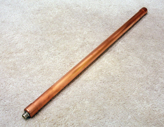
Figure 1. Finished product.

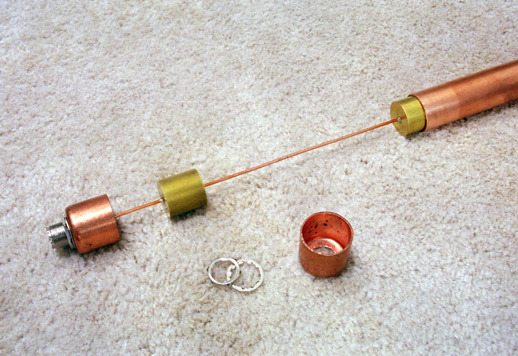
Figure 2. Interior construction.

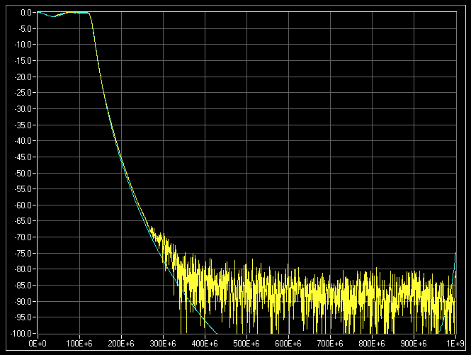
Figure 3. Frequency response. The yellow line is measured, the blue
line
is calculated.
Loss in-band is about -0.15 dB.
The filter
consists of a series of
transmission lines of precise
electrical
length and impedance. Common to all segments is the outer conductor,
which
is one long piece of 1" "red" copper pipe. The inner conductor is one
long
piece of #12 solid copper wire with segments of 1" OD brass cylinders
strung
on the wire like kabobs and soldered in place (with a torch). The wire
and brass cylinder assembly is fit into the copper pipe, suspended only
by a rolled-up sheet of teflon. UHF connectors are mounted in standard
copper pipe endcaps, which are fit on the two ends of the pipe,
completely
shielding the assembly.
The "red" ("type
M") copper pipe has
an ID of 1.055". The brass
cylinders
are 1" OD. The teflon sheet is specified to be 0.020", although we
measure
it to be about 0.021", so when it's rolled up inside the pipe, the
resulting
ID is just about 1.013". With some woggling, the brass just barely fits
inside. We ordered the teflon from Ridout Plastics as "TEF NAT 0.020 -
1801." We probably got 3 square feet. See:
http://www.ridoutplastics.com/teflonsheet.html
The total length
of #12 wire is
26.649". The brass cylinders,
drilled
down the center with a #44 bit, are threaded on and spaced along the
wire
such that the lengths are as follows:
Wire
2.071" 176.1 ps
Brass 1.000" 107.5 ps
Wire 5.848" 497.4 ps
Brass 2.000" 215.1 ps
Wire 4.811" 409.2 ps
Brass 2.000" 215.1 ps
Wire 5.848" 497.4 ps
Brass 1.000" 107.5 ps
Wire 2.071" 176.1 ps
-------------- ---------
Total 26.649" 2.402 ns
The wire sections
have a
characteristic impedance of about 153 ohms,
and the brass sections have a characteristic impedance of about 2.53
ohms.
The UHF connectors
at the ends are
Amphenol 83-878, which are rear
mount
so they can be soldered to the #12 wire before the endcaps are slipped
on. The pipe length is trimmed so that tightening the nuts on the UHF
connectors
just puts a little tension on the wire, holding the whole arrangement
firmly
together. Once finished and tested, the endcaps should be soldered on
to the 1" pipe to keep the ground connection solid.
The filter can
probably handle about
1000 W.

Figure 4. Filter topology and approximate discrete equivalents.


Figure 5. Cross sections.


